POSTED ON 2 October, 2017
This section explains how to create a bonding interface and the different options available.
Create Bonding
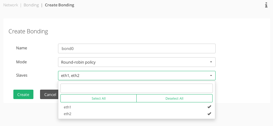
Find below the detailed options to create a bonding interface.
Name. System name for the new bonding interface.
Mode. The modes supported are described below.
- Round-robin policy. Transmit packets in sequential order from the first available slave through the last. This mode provides load balancing and fault tolerance.
- Active-backup policy. Only one slave in the bond is active. A different slave becomes active if, and only if, the active slave fails. The bond’s MAC address is externally visible on only one port (network adapter) to avoid confusing the switch. This mode provides fault tolerance. The primary option affects the behavior of this mode.
- XOR policy. Transmit based on source MAC address XOR’d with destination MAC address. This selects the same slave for each destination MAC address. This mode provides load balancing and fault tolerance.
- Broadcast policy. Transmits everything on all slave interfaces. This mode provides fault tolerance.
- EEE 802.3ad LACP. Creates aggregation groups that share the same speed and duplex settings. It uses all slaves in the active aggregator according to the 802.3ad specification. Pre-requisites:
- 1. Network interface support in the base drivers for retrieving the speed and duplex of each slave.
- 2. A switch that supports IEEE 802.3ad Dynamic link aggregation. Most switches will require some type of configuration to enable 802.3ad mode.
- Adaptive transmit load balancing.Channel bonding that does not require any special switch support. The outgoing traffic is distributed according to the current load (computed relative to the speed) on each slave. Incoming traffic is received by the current slave. If the receiving slave fails, another slave takes over the MAC address of the failed receiving slave. Pre-requisite: Base driver support for retrieving the speed of each slave.
- Adaptive load balancing. Includes Adaptive transmit load balancing plus receive load balancing for IPV4 traffic, and does not require any special switch support. The receive load balancing is achieved by ARP negotiation. The bonding driver intercepts the ARP Replies sent by the local system on their way out and overwrites the source hardware address with the unique hardware address of one of the slaves in the bonding such that different peers use different hardware addresses for the server.
Slaves. Selection of unused NIC interfaces to be part of the new Bonding interface.
Once all the required changes are done, press the Update button to create the new bonding interface.
Some notes:
- To restore your interface MAC addresses, you need to delete the bonding interface that is using the given interface. The bonding driver will then restore the MAC addresses that the member interfaces had before they were added to the bonding interface.
- The Bonding MAC address will be the taken from its first member device.
- The same member interface can be present only in one bonding interface.
- If one interface is part of a bonding interface then this interface will be locked.
- Bonding mode can’t be changed once the bonding interface is created, but member interfaces can be added or deleted in the bonding interface as needed.
Documentation under the terms of the GNU Free Documentation License.
